A lot of folks call regarding sleeving their engine blocks and are confused about wet vs. dry liners because they don’t understand the difference between them. Most aluminum production automotive engine blocks use dry gray iron cylinder liners for the piston and rings to ride on. A dry liner is either cast into or press fit into the aluminum bores of the block. The aluminum bores transfer heat from the liner to the coolant surrounding the aluminum bores. Some engines have wet liners, the Ferrari being one example.
The Darton MID sleeves convert what were dry liner blocks to wet liner. A wet liner is in direct contact with the cooling water. It is self supporting and does not rely on the aluminum casting to keep it round. For that reason it is much thicker wall and can be made thicker to hold more cylinder pressure. Wet liners have the added advantage of being easier to replace should one get damaged in service.

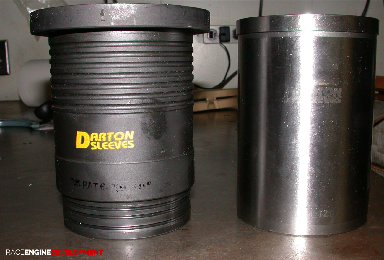
The photo shows a typical Darton MID wet liner on the left and a dry liner on the right.
Notice the cooling grooves in the MID liner to increase the surface area, and the o ring grooves in the lower section to prevent coolant loss to the crankcase. The basic design is typical of any wet sleeve as used in diesel tractor, bus, truck and train engines.
The MID sleeve has a feature added to the typical wet sleeve, the coolant groove with transfer holes through the sleeve flange. The sleeve flange itself supports the sleeve at the top thereby converting an open deck block to a closed deck. This design keeps the sleeve much rounder in service than a free standing sleeve either as cast in an open deck block or a replacement liner keeping the open deck design.

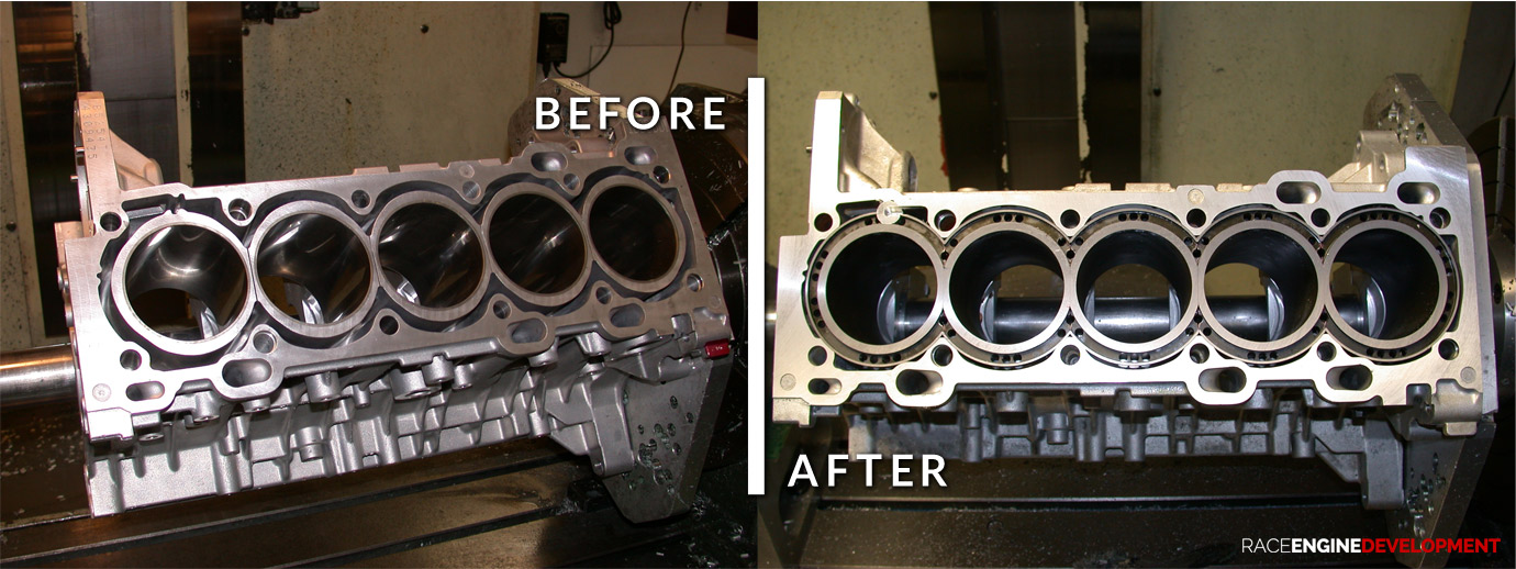
Here are before and after photos of an S60 Volvo engine block. Stock production / MID wet sleeve conversion.
You can clearly see the free standing unsupported cylinders in the production block compared to the MID sleeves which close off the gap between the cylinders and outer block wall thereby supporting the upper cylinder wall.
Now that I have explained something about the sleeves, I should add something regarding the material used to make the sleeves, either wet or dry. Both are made from the same strength ductile iron base material. The sleeves are spun cast (molten iron is poured into a spinning mold) one at a time to remove impurities and provide a denser casting. The ductile iron material is roughly four times stronger (135,000 lbs tensile strength) than a gray iron liner used in a typical production casting or after market repair sleeve. Not only is the material of higher tensile strength, but ductile as well as in it’s name. That means it will bend a considerable amount before it breaks. A gray iron sleeve offers little ductility and will shatter when it’s strength limit is exceeded. Darton makes 100% of the sleeves used by all the NHRA top fuel and funny car teams because they have the best material and finished product available.
What is required in the way of equipment and experience to correctly sleeve a block?
You need a CNC bed mill or machining center large enough to fixture the intended block to be sleeved. The machine must have flood coolant for thermal stability of the block casting from beginning to end of the machining process. An aluminum engine block casting machined dry will expand during the machining process due to heat generated from the friction during machining. The expansion will make it impossible to hold the required tolerances for a successful sleeve installation.

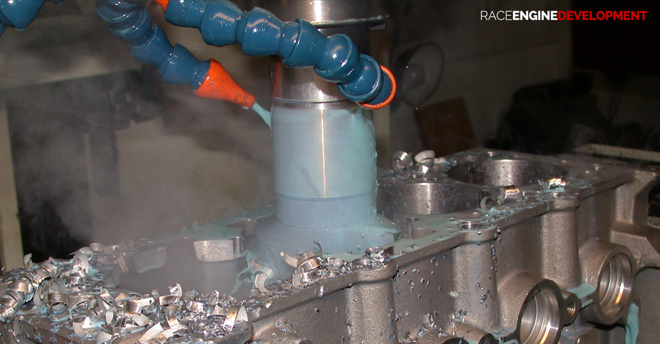
Here is a photo of a Ford 5.4 GT 40 casting being roughed out for MID sleeve installation. You can see the coolant vapor as the coolant is doing it’s job of taking the heat out of the casting during machining.
The bore center to center tolerance for MID sleeve block machining is +- .0005″ or half a thosandth of an inch. The bore diameters where the sleeve fits into the lower block casting is +-.00025″ or a quarter of a thousandth of an inch. The CNC must be well maintained and equipped with only the best boring heads, I use Kaiser, to enable duplication of sizes from bore to bore and bank to bank. Failure to hold tolerance will result in bores going out of round and tapered in service. You can’t seal piston rings to make power with an out of round or tapered bore.

Flood coolant will minimize the stresses induced into the casting during machining. Stress will be induced regardless and new castings have inherent stress in the casting. If these stress forces are not reduced, the casting will warp in service and the result can be cylinder walls going out of round .004″ to .005″ which is obviously not a desirable situation. So what I do is to first rough out the casting, then remove the casting from the CNC and use vibratory stress relief to eliminate as much of the inherent or induced stress as possible before finish machining is done for sleeve installation. I use a Formula 62 Vibratory Stress Relief machine made by Stress Relief Engineering to accomplish this task.


This machine will vibrate the block at the natural harmonic frequency of the casting. According to the manufacturer, this is the best method to reduce stress. This machine is used by many well known manufacturers including Boeing, General Motors, Alcoa and a long list of others. Here is a link to Stress Relief Engineering for more information on the reasons for stress relief and how this is accomplished with their equipment: http://www.stressreliefengr.com/about.html
After stress relief the block is set up on the CNC for final machining to size for sleeve installation. The sleeves are measured for size, sizes may vary slightly in a set, and the block is bored to a specific size to properly fit each sleeve. That’s why one needs a very good boring head as the size may have to be adjusted from hole to hole to get the correct size for that particular sleeve. There is no close enough here. I’m not happy unless things come out perfect.
When the machine work to install the sleeves is finished, the block is deburred and cleaned for sleeve installation. The sleeves are not pressed into the block, that’s a no no. There is a specific clearance that is used else the sleeves will distort or the block casting will crack between the bores. The correct procedure was developed here. Still some folks seem to think they know better than the folks who designed the sleeves and hold the patent. This results in failure of the engine at worst and poor performance or leaking at best. I have fixed or replaced dozens of blocks for folks through the years who had their blocks machined at the wrong place.
Here is a photo of the block fitted with MID sleeves prior to decking and finish boring. The block will be stress relieved one more time with sleeves installed prior to decking and finish boring. The final stress relief will reduce the minimal stress induced during the finish machining process as well as the any stress in the sleeves themselves.

